
Monocular Visual Odometry System that can be built using off the shelves components and open-source software developed by the ETH Zurich Autonomous Systems Lab. The software is running on a AAEON PICO-APL3 based Companion Computer running UBUNTU 16.04 and ROS KINETIC. The VIO system is controlling a Linux Based BeagleBone Flight Controller installed on 450 Size Quadcopter.
Visual Inertial Odometry
Using a camera system and an Inertial Measurement Unit - IMU , we can estimate a 6 DoF (Degree of Freedom) state corresponding to 3D position (xyz) and 3 Axis rotation (roll-pitch-yaw), in relation to a fixed reference W (World/ Map / Home). This state estimation is then transmitted to the flight controler using the MavLink message [https://mavlink.io/en/messages/common.html#VISION_POSITION_ESTIMATE 4 ]
corresponding to the actual vehicle state in space
The system can be broken down in 3 major components:
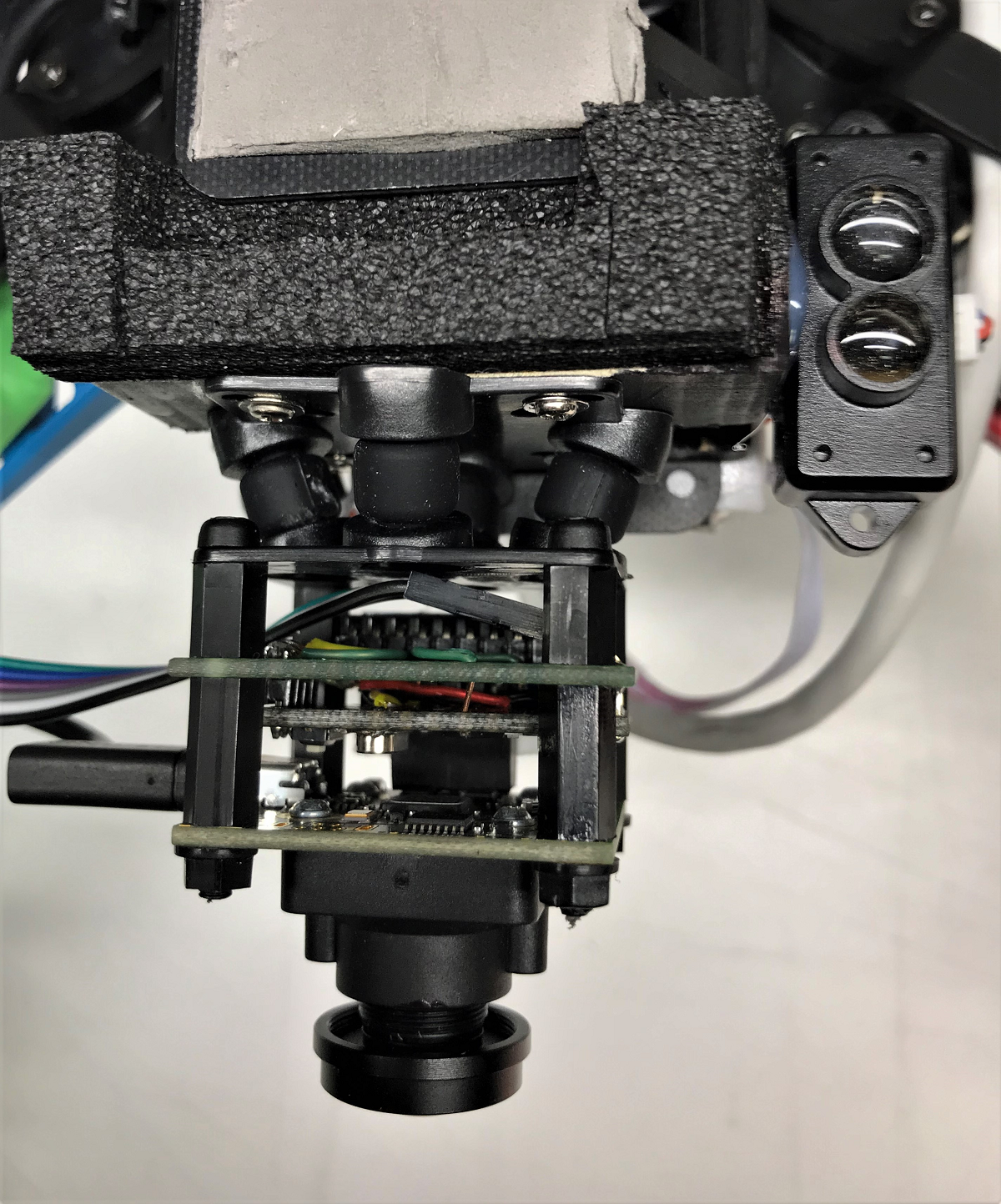
- The Visual Inertial sensor : A Global Shutter USB Camera with a MPU9250 IMU connected to an Arduino
- The state estimator : ROVIO (Robust Visual Inertial Odometry) that runs on the Companion Computer
- The Flight Controller : On this system I am using the BeagleBone Black with a DIY sensors cape = The BBBMINI
- This system requires a powerful Companion Computer in order to process and output state estimate on real-time with good refresh rate and minimum delay. I installed a AAEON PICO-APL3 with a Pentium N4200 and 4 Gb RAM, loaded UBUNTU 16.04 and ROS KINETIC. https://www.aaeon.com/en/p/pico-itx-boards-pico-apl3
Once the lab tests are complete and the operational envelope is defined, this is the time to test in real life on a flying vehicle. My test quadcopter is a Q450 (or 500 depending on the supplier) with 2412 type engines turning 10 1/2’’ propellers powered by 4,000mA - 3S packs.
The total weight of the configuration is 1,55 Kg without battery and 1,86Kg with the pack, making it quite heavy for a nylon frame. The experiments being accomplished in my garage, I don’t plan to get a bigger frame as this configuration is intended to be a technological demonstrator and not a fully functional solution.

I have distributed the weight on the longitudinal axis and used the battery pack for balance. The AAEON PICO-APL3 Pentium board and the 12 V 5 A Step Up-Down regulator are mounted on corrugated board that is sliding along the 10 mm tubes attached to the frame. The Battery holder is attached to the same tubes and can slide to adjust for a “0” CoG.
Static test
The camera was mounted on a tilt adjustable holder but that proved to be a source of vibration that got ROVIO loosing track. The solution is to mount the camera on a damping platform that isolates the camera and particularly the IMU sensor from the vehicle vibrations.
The walk test
Once all the signal are optimal and the system start OK, it is time to simulate a flight by ‘‘walking’’ the quadcopter, take the Quadcopter, hold it about 1 meter and do a circle, square, figure 8 or any pattern you like. The vehicle on the map should move accordingly without too much distortion or overshoot.
Initial test
As explained above, we need to confirm the system work OK before powering the quadcopter.
Once this is confirmed, I prefer to takeoff in stabilize to make sure the quadcopter is stable at 1 Meter facing the targets and then I switch to Al-Hold just to adjust the correct power for level flight (you can actually see the overloaded Q450 oscillation @ 0:30). As the prototype is so heavy, altitude is holding at above average power level so I prefer having it stabilized before switching to loiter. Then you take a look at Mission Planner Map , for a confirmation that ROVIO is still tracking and then you switch Loiter, getting ready to switch back to Att-Hold if the Quadcopter starts drifting.
Here is a video of the test:
https://youtu.be/r9-iDeRL8LQ

The configurations files , the modified sources and lab notes are on github: https://github.com/patrickpoirier51/ROVIO
That completes what is reasonably possible to accomplish with a Q450 autonomously fling in my Garage , aka the ThunderDrone. The next steps will involve outdoor testing, but it will take a few more weeks as it is still snowing outside…
I just hope that this blog was helpful in explaining how you can build , test and fly a Monocular Robust Visual Intertial Odometry system using affordable components and a powerfull OnBoard Companion Computer like the AAEON PICO-APL3.
